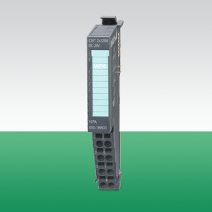
Модуль управления двигателем постоянного тока, 2 канала 24 В/1,5 А с обратной связью через энкодер, 4 дискретных входа/выхода 24 В пост. тока, частота ШИМ 32 кГц
|
Наименование
|
FM 054 2xDC Motor |
|
Тип
|
054-1CB00 |
|
Габаритные размеры, В х Ш х Г, мм
|
12.9 mm x 109 mm x 76.5 mm |
|
Температура окружающей среды
|
0 °C .. 60 °C |
 |
|
Status indication
 |
RUN | MF | Description | |
| green | red |
|
||
| ● | ○ | Bus communication is OK Module status is OK |
||
| ● | ● |
Bus communication is OK |
||
| ○ | ● |
Bus communication is not possible |
||
| ○ | ○ | Error at bus power supply | ||
| X | B |
Error in configuration |
||
| PWRA | green |
○ |
The state of the module is beyond |
|
|
B |
Drive 1 is in state ‘Switched on’ | |||
|
● |
Drive 1 is in state ‘Operation enabled’ | |||
| PWRB | green |
○ |
The state of drive 2 is beyond ‘Switched |
|
|
B |
Drive 2 is in state ‘Switched on’ |
|||
|
● |
Drive 2 is in state ‘Operation enabled’ | |||
| ERRA | red |
○ |
No error drive 1 |
|
|
B |
Warning drive 1: 0x80 |
|||
|
● |
Error drive 1: 0x08 |
|||
| ERRB | red |
○ |
No error drive 2 | |
| B | Warning drive 2: 0x80 | |||
| ● | Error drive 2: 0x08 | |||
| I/O1 | green |
○ |
Digital input/output 1 has "0" signal |
|
|
● |
Digital input/output 1 has "1" signal |
|||
| I/O2 | green |
○ |
Digital input/output 2 has "0" signal |
|
|
● |
Digital input/output 2 has "1" signal |
|||
| I/O3 | green | ○ | Digital input/output 3 has "0" signal | |
| ● | Digital input/output 3 has "1" signal | |||
| I/O4 | green | ○ | Digital input/output 4 has "0" signal | |
| ● | Digital input/output 4 has "1" signal | |||
| on: ● | off: ○ | blinking:: B | not relevant: X | ||||
Pin assignment
| PM - Power module | Pos. | Function |
Type |
Description |
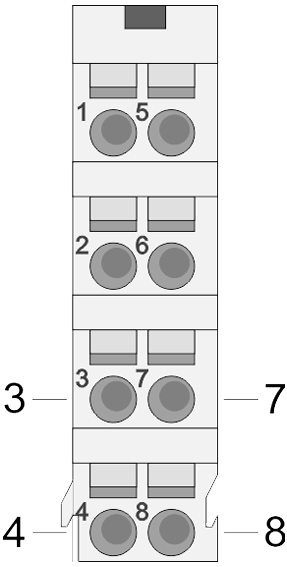 |
3 | I/O1 | I |
Encoder function drive 1 |
| 4 | I/O3 | I |
Encoder function drive 1 |
|
| 7 | I/O2 | I |
Encoder function drive 2 |
|
| 8 | I/O4 | I |
Encoder function drive 2 |
I: Input, O: Output
Order no. |
054-1CB00 |
| Type | FM 054 |
| Module ID | 0982 6800 |
General information |
|
| Note | - |
| Features | 2-channel with feedback 4 inputs/outputs DC 24V, which can be used as encoder inputs PWM clock frequency 32 kHz |
Current consumption/power loss |
|
| Current consumption from backplane bus | 50 mA |
| Power loss | 1 W |
Technical data digital inputs |
|
| Number of inputs | 4 |
| Cable length, shielded | 1000 m |
| Cable length, unshielded | 600 m |
| Rated load voltage | - |
| Current consumption from load voltage L+ (without load) | - |
| Rated value | DC 20.4...28.8 V |
| Input voltage for signal "0" | DC 11...28.8 V |
| Input voltage for signal "1" | DC 0...5 V |
| Input voltage hysteresis | - |
| Frequency range | - |
| Input resistance | - |
| Input current for signal "1" | 3 mA |
| Connection of Two-Wire-BEROs possible |  |
| Max. permissible BERO quiescent current | 0.5 mA |
| Input delay of "0" to "1" | 1.5 ms |
| Input delay of "1" to "0" | 1.5 ms |
| Number of simultaneously utilizable inputs horizontal configuration | 2 |
| Number of simultaneously utilizable inputs vertical configuration | 2 |
| Input characteristic curve | IEC 61131-2, type 3 |
| Initial data size | 4 Bit |
Technical data digital outputs |
|
| Number of outputs | 4 |
| Cable length, shielded | 1000 m |
| Cable length, unshielded | 600 m |
| Rated load voltage | DC 20.4...28.8 V |
| Reverse polarity protection of rated load voltage | - |
| Current consumption from load voltage L+ (without load) | - |
| Output current at signal "1", rated value | 500 mA |
| Output delay of "0" to "1" | 1.5 ms |
| Output delay of "1" to "0" | 1.5 ms |
| Minimum load current | - |
| Lamp load | 10 W |
| Parallel switching of outputs for redundant control of a load | not possible |
| Parallel switching of outputs for increased power | not possible |
| Actuation of digital input | |
| Switching frequency with resistive load | max. 300 Hz |
| Switching frequency with inductive load | max. 0.5 Hz |
| Switching frequency on lamp load | max. 10 Hz |
| Internal limitation of inductive shut-off voltage | L+ (-45 V) |
| Short-circuit protection of output | yes, electronic |
| Trigger level | 1 A |
| Number of operating cycle of relay outputs | - |
| Switching capacity of contacts | - |
| Output data size | - |
Status information, alarms, diagnostics |
|
| Status display | green LED per channel |
| Interrupts | yes, parameterizable |
| Process alarm | no |
| Diagnostic interrupt | yes, parameterizable |
| Diagnostic functions | yes |
| Diagnostics information read-out | possible |
| Supply voltage display | green LED |
| Group error display | red LED |
| Channel error display | red LED per channel |
Isolation |
|
| Between channels | - |
| Between channels of groups to | - |
| Between channels and backplane bus | |
| Insulation tested with | AC 500 V |
Technical data positioning module |
|
| Number of channels | 2 |
| Input voltage (rated value) | DC 24 V |
| Input voltage (permitted range) | DC 20.4...28.8 V |
| Motor current | 1.5 A |
| Power stage | 2x Full bridge PWM |
| Short-circuit protection | |
| Brake-Chopper required | - |
| PWM frequency | 32 kHz |
| Pulse train frequency | - |
| Micro steps | - |
| Steps per rotation | - |
| Type of encoder | A/B phase 24V single ended |
| Encoder frequency | 100 kHz |
| Encoder resolution | 24 Bit |
| Control type | closed loop |
| Temperature sensor | |
Operating modes position functions |
|
| Homing via homing switch | |
| Positioning via torque | |
| Positioning without encoder | |
| Positioning with encoder | |
| Speed control | |
| Torque control | |
Housing |
|
| Material | PPE / PPE GF10 |
| Mounting | Profile rail 35 mm |
Mechanical data |
|
| Dimensions (WxHxD) | 12.9 mm x 109 mm x 76.5 mm |
| Weight | 62 g |
Environmental conditions |
|
| Operating temperature | 0 °C to 60 °C |
| Storage temperature | -25 °C to 70 °C |
Certifications |
|
| UL certification | in preparation |
| KC certification | in preparation |
| Order no. | Name/Description | |
|---|---|---|
|
050-1BA00 |
FM 050 - Counter module␍␍␍ 1 Counter 32 Bit (AB) DC 24 V |
|
|
050-1BA10 |
FM 050 - Counter module 1 Counter 32 Bit (AB) DC 5 V (difference signal) |
|
|
050-1BB00 |
FM 050 - Counter module 2 Counter 32 Bit (AB) DC 24 V |
|
|
050-1BB30 |
FM 050 - Counter module Eco 2 Counter 32 Bit (AB) DC 24 V |
|
|
050-1BB40 |
FM 050 - Frequency measurement 2 channels 24 Bit DC 24 V |
|
|
050-1BS00 |
FM 050S - SSI module SSI - Encoder Master or slave mode Encoder frequency 125 kHz...2 MHz μs time stamp for encoder value |
|
|
054-1BA00 |
FM054 – Stepper motor module 1-channel with feedback 4 inputs/outputs DC 24V, which can be used as encoder inputs Power control frequency 32 kHz Step pattern 64 times microstepping |
|
|
054-1CB00 |
FM054 - DC motor module 2-channel with feedback 4 inputs/outputs DC 24V, which can be used as encoder inputs PWM clock frequency 32 kHz |
|
|
054-1DA00 |
FM054 - Pulse Train Output Module 1-channel RS422 with feedback 4 configurable in-/outputs I/O1 ... I/O4 Operating modes: CW/CCW, PLS/DIR, ENC/SIM |
|

Изделие: 050-1BA10
Модуль счетчика: 1 канал (AB), 32 разряда, входной дифференциальный сигнал 5 В пост. тока с частотой до 2 МГц
Изделие: 054-1DA00
Модуль импульсного управления (Pulse Train) электроприводом, 1 канал RS-422 (до 1 Мгц) с обратной связью, 4 конфигурируемых DIO, режимы работы: CW/CCW, PLS/DIR, ENC/SIM
Изделие: 050-1BB00
Модуль счетчика: 2 канала (AB), 32 разряда, входной сигнал 24 В пост. тока с частотой до 400 кГц
Изделие: 050-1BB40
Модуль измерения частоты: 2 канала, 24 разряда, входной сигнал 24 В пост. тока с частотой до 600 кГц
г. Алматы, Ауэзовский район
ул. Толе Би 302, Литер "Д"
офис № 205
+7 (727) 268-0321
+7 (701) 082-9486
+7 (707) 493-7210
+7 (727) 268-0321
info@controllink.kz