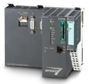
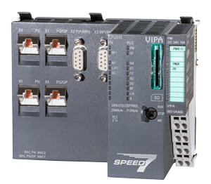
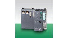
CPU 013C (013-CCF0R00)
Модуль CPU 013C со встроенными IO
Компактный процессорный модуль CPU 013C имеет на борту встроенные каналы дискретного и аналогового ввода-вывода, а также конфигурируемые специализированные каналы для реализации различных технологических функций. Наличие встроенных сигнальных входов-выходов позволяет использовать CPU 013C в качестве функционально законченного блока управления в системах промышленной автоматизации, системах автоматизации зданий, конвейерных системах и т.д.
При необходимости, функциональные возможности CPU 013C могут быть существенно увеличены с помощью модулей расширения серии SLIO всех типов. При этом контроллер обеспечивает также обмен данными в сетях Ethernet и PROFIBUS DP, а также через последовательные соединения типа PtP с интерфейсом RS-485.
Основные характеристики
| Модуль CPU 015 | Описание | |
 |
|
Интерфейсы
|
X1/X2 Ethernet PG/OP |
Описание |
X3 PtP(MPI) |
Описание | |||
 |
|
 |
|
X4: Connector

| Pos. | Function |
Type |
Description |
| 1 | AI 0 | I | AI0: Analog input AI 0 |
| 2 | AI 1 | I | AI1: Analog input AI 1 |
| 3 | Analog 0V | I | 4M: GND for analog inputs |
| 4 | DI 0 | I | +0.0: Digital input DI 0 / Counter 0 (A) * |
| 5 | DI 1 | I | +0.1: Digital input DI 1 / Counter 0 (B) / Frequency 0 * |
| 6 | DI 2 | I | +0.2: Digital input DI 2 |
| 7 | DI 3 | I | +0.3: Digital input DI 3 / Counter 1 (A) * |
| 8 | DI 4 | I | +0.4: Digital input DI 4 / Counter 1 (B) / Frequency 1 * |
| 9 | DI 5 | I | +0.5: Digital input DI 5 |
| 10 | DI 6 | I | +0.6: Digital input DI 6 / Counter 2 (A) * |
| 11 | DI 7 | I | +0.7: Digital input DI 7 / Counter 2 (B) / Frequency 2 * |
| 12 | DI 8 | I | +1.0: Digital input DI 8 |
| 13 | DI 9 | I | +1.1: Digital input DI 9 / Counter 3 (A) * |
| 14 | DI 10 | I | +1.2: Digital input DI 10 / Counter 3 (B) / Frequency 3 * |
| 15 | DI 11 | I | +1.3: Digital input DI 11 / Gate 3 * |
| 16 | DI 12 | I | +1.4: Digital input DI 12 |
| 17 | DI 13 | I | +1.5: Digital input DI 13 |
| 18 | DI 14 | I | +1.6: Digital input DI 14 |
| 19 | DI 15 | I | +1.7: Digital input DI 15 / Latch 3 * |
| 20 | DC 24V | I | 5L+: DC 24V for onboard DI power section supply |
| 21 | 0 V | I | 5M: GND for onboard DI power section supply |
*) Max. input frequency 100kHz otherwise 1kHz.
X5: Connector

| Pos. | Function |
Type |
Description |
| 1 | AI 0 | I | 1L+: DC 24V for electronic section supply |
| 2 | AI 1 | I | 1M: GND for electronic section supply |
| 3 | --- | --- | reserved |
| 4 | DC 24V | O | S+: DC 24V for sensor |
| 5 | 0V | O | 1M: GND for sensor |
| 6 | DI 0 | O | +0.0: Digital output DO 0 / PWM 0 / Output channel counter 0 |
| 7 | DI 1 | O | +0.1: Digital output DO 1 / PWM 1 / Output channel counter 1 |
| 8 | DI 2 | O | +0.2: Digital output DO 2 / Output channel counter 2 |
| 9 | DI 3 | O | +0.3: Digital output DO 3 / Output channel counter 3 |
| 10 | DI 4 | O | +0.4: Digital output DO 4 |
| 11 | DI 5 | O | +0.5: Digital output DO 5 |
| 12 | DI 6 | O | +0.6: Digital output DO 6 |
| 13 | DI 7 | O | +0.7: Digital output DO 7 |
| 14 | DI 8 | O | +1.0: Digital output DO 8 |
| 15 | DI 9 | O | +1.1: Digital output DO 9 |
| 16 | DI 10 | O | +1.2: Digital output DO 10 |
| 17 | DI 11 | O | +1.3: Digital output DO 11 |
| 18 | DC 24V | I | 2L+: DC 24V for onboard DO power section supply |
| 19 | 0 V | I | 2M: GND for onboard DO power section supply / GND PWM |
| 20 | DC 24V | I | 3L+: DC 24V for SLIO bus power section supply |
| 21 | 0 V | I | 3M: GND for SLIO bus power section supply |
Order no. |
013-CCF0R00 |
| Type | CPU 013C |
| Module ID | - |
General information |
|
| Note | - |
| Features | SPEED7 technology 16 x DI, 12 x DO, 2 x AI, from which are 4 input channels parameterizable for counters and frequency measurement and 2 Output channels for PWM 64 kB work memory Memory extension (max. 128 kB) optionell PROFIBUS-DP slave / PtP (switchable) |
Technical data power supply |
|
| Power supply (rated value) | DC 24 V |
| Power supply (permitted range) | DC 20.4...28.8 V |
| Reverse polarity protection |  |
| Current consumption (no-load operation) | 120 mA |
| Current consumption (rated value) | 360 mA |
| Inrush current | 3 A |
| I²t | 0.1 A²s |
| Max. current drain at backplane bus | 1 A |
| Max. current drain load supply | 6 A |
| Power loss | 7 W |
Technical data digital inputs |
|
| Number of inputs | 16 |
| Cable length, shielded | 1000 m |
| Cable length, unshielded | 600 m |
| Rated load voltage | DC 24 V |
| Reverse polarity protection of rated load voltage | |
| Current consumption from load voltage L+ (without load) | 25 mA |
| Rated value | DC 24 V |
| Input voltage for signal "0" | DC 0...5 V |
| Input voltage for signal "1" | DC 15...28.8 V |
| Input voltage hysteresis | - |
| Frequency range | - |
| Input resistance | - |
| Input current for signal "1" | 3 mA |
| Connection of Two-Wire-BEROs possible | |
| Max. permissible BERO quiescent current | 0.5 mA |
| Input delay of "0" to "1" | 3 µs – 15 ms / 0.5 ms – 15 ms |
| Input delay of "1" to "0" | 3 µs – 15 ms / 0.5 ms – 15 ms |
| Number of simultaneously utilizable inputs horizontal configuration | 16 |
| Number of simultaneously utilizable inputs vertical configuration | 16 |
| Input characteristic curve | IEC 61131-2, type 1 |
| Initial data size | 16 Bit |
Technical data digital outputs |
|
| Number of outputs | 12 |
| Cable length, shielded | 1000 m |
| Cable length, unshielded | 600 m |
| Rated load voltage | DC 24 V |
| Reverse polarity protection of rated load voltage | |
| Current consumption from load voltage L+ (without load) | 20 mA |
| Total current per group, horizontal configuration, 40°C | 6 A |
| Total current per group, horizontal configuration, 60°C | 6 A |
| Total current per group, vertical configuration | 6 A |
| Output voltage signal "1" at min. current | L+ (-0.8 V) |
| Output voltage signal "1" at max. current | L+ (-0.8 V) |
| Output current at signal "1", rated value | 0.5 A |
| Output current, permitted range to 40°C | 5 mA to 0.6 A |
| Output current, permitted range to 60°C | 5 mA to 0.6 A |
| Output current at signal "0" max. (residual current) | 0.5 mA |
| Output delay of "0" to "1" | 2 µs / 30 µs |
| Output delay of "1" to "0" | 3 µs / 175 µs |
| Minimum load current | - |
| Lamp load | 10 W |
| Parallel switching of outputs for redundant control of a load | not possible |
| Parallel switching of outputs for increased power | not possible |
| Actuation of digital input | |
| Switching frequency with resistive load | max. 1000 Hz |
| Switching frequency with inductive load | max. 0.5 Hz |
| Switching frequency on lamp load | max. 10 Hz |
| Internal limitation of inductive shut-off voltage | L+ (-45 V) |
| Short-circuit protection of output | yes, electronic |
| Trigger level | 1 A |
| Number of operating cycle of relay outputs | - |
| Switching capacity of contacts | - |
| Output data size | 12 Bit |
Technical data analog inputs |
|
| Number of inputs | 2 |
| Cable length, shielded | 200 m |
| Rated load voltage | - |
| Reverse polarity protection of rated load voltage | - |
| Current consumption from load voltage L+ (without load) | - |
| Voltage inputs | |
| Min. input resistance (voltage range) | 100 kΩ |
| Input voltage ranges | 0 V ... +10 V |
| Operational limit of voltage ranges | +/-3.5% |
| Operational limit of voltage ranges with SFU | - |
| Basic error limit voltage ranges | +/-3.0% |
| Basic error limit voltage ranges with SFU | - |
| Destruction limit voltage | max. 30V |
| Current inputs | - |
| Max. input resistance (current range) | - |
| Input current ranges | - |
| Operational limit of current ranges | - |
| Operational limit of current ranges with SFU | - |
| Basic error limit current ranges | - |
| Radical error limit current ranges with SFU | - |
| Destruction limit current inputs (electrical current) | - |
| Destruction limit current inputs (voltage) | - |
| Resistance inputs | - |
| Resistance ranges | - |
| Operational limit of resistor ranges | - |
| Operational limit of resistor ranges with SFU | - |
| Basic error limit | - |
| Basic error limit with SFU | - |
| Destruction limit resistance inputs | - |
| Resistance thermometer inputs | - |
| Resistance thermometer ranges | - |
| Operational limit of resistance thermometer ranges | - |
| Operational limit of resistance thermometer ranges with SFU | - |
| Basic error limit thermoresistor ranges | - |
| Basic error limit thermoresistor ranges with SFU | - |
| Destruction limit resistance thermometer inputs | - |
| Thermocouple inputs | - |
| Thermocouple ranges | - |
| Operational limit of thermocouple ranges | - |
| Operational limit of thermocouple ranges with SFU | - |
| Basic error limit thermoelement ranges | - |
| Basic error limit thermoelement ranges with SFU | - |
| Destruction limit thermocouple inputs | - |
| Programmable temperature compensation | - |
| External temperature compensation | - |
| Internal temperature compensation | - |
| Technical unit of temperature measurement | - |
| Resolution in bit | 12 |
| Measurement principle | successive approximation |
| Basic conversion time | 0.5 ms |
| Noise suppression for frequency | 40 dB |
| Initial data size | 4 Byte |
Technical data analog outputs |
|
| Number of outputs | - |
| Cable length, shielded | - |
| Rated load voltage | - |
| Reverse polarity protection of rated load voltage | - |
| Current consumption from load voltage L+ (without load) | - |
| Voltage output short-circuit protection | - |
| Voltage outputs | - |
| Min. load resistance (voltage range) | - |
| Max. capacitive load (current range) | - |
| Max. inductive load (current range) | - |
| Output voltage ranges | - |
| Operational limit of voltage ranges | - |
| Basic error limit voltage ranges with SFU | - |
| Destruction limit against external applied voltage | - |
| Current outputs | - |
| Max. in load resistance (current range) | - |
| Max. inductive load (current range) | - |
| Typ. open circuit voltage current output | - |
| Output current ranges | - |
| Operational limit of current ranges | - |
| Radical error limit current ranges with SFU | - |
| Destruction limit against external applied voltage | - |
| Settling time for ohmic load | - |
| Settling time for capacitive load | - |
| Settling time for inductive load | - |
| Resolution in bit | - |
| Conversion time | - |
| Substitute value can be applied | - |
| Output data size | - |
Technical data counters |
|
| Number of counters | 4 |
| Counter width | 32 Bit |
| Maximum input frequency | 100 kHz |
| Maximum count frequency | 400 kHz |
| Mode incremental encoder | |
| Mode pulse / direction | |
| Mode pulse | |
| Mode frequency counter | |
| Mode period measurement | |
| Gate input available | |
| Latch input available | |
| Reset input available | - |
| Counter output available | |
Load and working memory |
|
| Load memory, integrated | 128 KB |
| Load memory, maximum | 128 KB |
| Work memory, integrated | 64 KB |
| Work memory, maximal | 128 KB |
| Memory divided in 50% program / 50% data | |
| Memory card slot | SD/MMC-Card with max. 2 GB |
Hardware configuration |
|
| Racks, max. | 5 |
| Modules per rack, max. | total max. 64 minus number line extensions |
| Number of integrated DP master | - |
| Number of DP master via CP | - |
| Operable function modules | 64 |
| Operable communication modules PtP | 64 |
| Operable communication modules LAN | - |
Status information, alarms, diagnostics |
|
| Status display | yes |
| Interrupts | yes |
| Process alarm | yes |
| Diagnostic interrupt | yes |
| Diagnostic functions | yes, parameterizable |
| Diagnostics information read-out | possible |
| Supply voltage display | green LED |
| Group error display | red SF LED |
| Channel error display | red LED per group |
Isolation |
|
| Between channels | |
| Between channels of groups to | 16 |
| Between channels and backplane bus | |
| Between channels and power supply | - |
| Max. potential difference between circuits | DC 75 V/ AC 50 V |
| Max. potential difference between inputs (Ucm) | - |
| Max. potential difference between Mana and Mintern (Uiso) | - |
| Max. potential difference between inputs and Mana (Ucm) | - |
| Max. potential difference between inputs and Mintern (Uiso) | - |
| Max. potential difference between Mintern and outputs | - |
| Insulation tested with | DC 500 V |
Command processing times |
|
| Bit instructions, min. | 0.02 µs |
| Word instruction, min. | 0.02 µs |
| Double integer arithmetic, min. | 0.02 µs |
| Floating-point arithmetic, min. | 0.12 µs |
Timers/Counters and their retentive characteristics |
|
| Number of S7 counters | 512 |
| Number of S7 times | 512 |
Data range and retentive characteristic |
|
| Number of flags | 8192 Byte |
| Number of data blocks | 1024 |
| Max. data blocks size | 64 KB |
| Max. local data size per execution level | 4096 Byte |
Blocks |
|
| Number of OBs | 22 |
| Number of FBs | 1024 |
| Number of FCs | 1024 |
| Maximum nesting depth per priority class | 16 |
| Maximum nesting depth additional within an error OB | 4 |
Time |
|
| Real-time clock buffered | |
| Clock buffered period (min.) | 30 d |
| Accuracy (max. deviation per day) | 10 s |
| Number of operating hours counter | 8 |
| Clock synchronization | |
| Synchronization via MPI | Master/Slave |
| Synchronization via Ethernet (NTP) | no |
Address areas (I/O) |
|
| Input I/O address area | 2048 Byte |
| Output I/O address area | 2048 Byte |
| Input process image maximal | 2048 Byte |
| Output process image maximal | 2048 Byte |
| Digital inputs | 528 |
| Digital outputs | 524 |
| Digital inputs central | 528 |
| Digital outputs central | 524 |
| Integrated digital inputs | 16 |
| Integrated digital outputs | 12 |
| Analog inputs | 514 |
| Analog outputs | 256 |
| Analog inputs, central | 514 |
| Analog outputs, central | 256 |
| Integrated analog inputs | 2 |
| Integrated analog outputs | - |
| Number of outputs | 1 |
| Output voltage (typ) | L+ (-1.5 V) |
| Output voltage (rated value) | 300 mA |
| Short-circuit protection | yes, electronic |
| Binding of potential | Power supply of PLC |
Communication functions |
|
| PG/OP channel | |
| Global data communication | |
| Number of GD circuits, max. | 8 |
| Size of GD packets, max. | 54 Byte |
| S7 basic communication | |
| S7 basic communication, user data per job | 76 Byte |
| S7 communication | |
| S7 communication as server | |
| S7 communication as client | - |
| S7 communication, user data per job | 160 Byte |
| Number of connections, max. | 32 |
PWM data |
|
| PWM channels | 2 |
| PWM time basis | 1 µs / 0.1 ms / 1 ms |
| Period length | 50µs...65.535ms / 0.1...87ms / 1...87ms |
| Minimum pulse width | 0...0.5 * Period duration |
| Type of output | Highside |
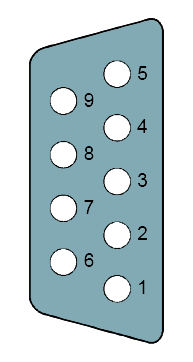
Functionality Sub-D interfaces |
|
| Type | X3 |
| Type of interface | RS485 |
| Connector | Sub-D, 9-pin, female |
| Electrically isolated | |
| MPI | |
| MP²I (MPI/RS232) | - |
| DP master | - |
| DP slave | optional |
| Point-to-point interface | |
| 5V DC Power supply | max. 90mA, isolated |
| 24V DC Power supply | max. 100mA, non-isolated |
| Type | - |
| Type of interface | - |
| Connector | - |
| Electrically isolated | - |
| MPI | - |
| MP²I (MPI/RS232) | - |
| DP master | - |
| DP slave | - |
| Point-to-point interface | - |
| 5V DC Power supply | - |
| 24V DC Power supply | - |
Functionality MPI |
|
| Number of connections, max. | 32 |
| PG/OP channel | |
| Routing | |
| Global data communication | |
| S7 basic communication | |
| S7 communication | |
| S7 communication as server | |
| S7 communication as client | - |
| Transmission speed, min. | 19.2 kbit/s |
| Transmission speed, max. | 12 Mbit/s |
Functionality PROFIBUS slave |
|
| PG/OP channel | |
| Routing | |
| S7 communication | |
| S7 communication as server | |
| S7 communication as client | - |
| Direct data exchange (slave-to-slave communication) | - |
| DPV1 | |
| Transmission speed, min. | 9.6 kbit/s |
| Transmission speed, max. | 12 Mbit/s |
| Automatic detection of transmission speed | |
| Transfer memory inputs, max. | 244 Byte |
| Transfer memory outputs, max. | 244 Byte |
| Address areas, max. | 32 |
| User data per address area, max. | 32 Byte |
Point-to-point communication |
|
| PtP communication | |
| Interface isolated | |
| RS232 interface | - |
| RS422 interface | - |
| RS485 interface | |
| Connector | Sub-D, 9-pin, female |
| Transmission speed, min. | 150 bit/s |
| Transmission speed, max. | 115.5 kbit/s |
| Cable length, max. | 500 m |
Point-to-point protocol |
|
| ASCII protocol | |
| STX/ETX protocol | |
| 3964(R) protocol | |
| RK512 protocol | - |
| USS master protocol | |
| Modbus master protocol | |
| Modbus slave protocol | |
| Special protocols | - |
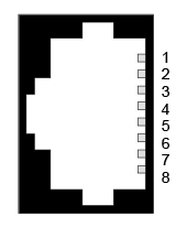
Functionality RJ45 interfaces |
|
| Type | X1/X2 |
| Type of interface | Ethernet 10/100 MBit Switch |
| Connector | 2 x RJ45 |
| Electrically isolated | |
| PG/OP channel | |
| Number of connections, max. | 4 |
| Productive connections | - |
| Type | - |
| Type of interface | - |
| Connector | - |
| Electrically isolated | - |
| PG/OP channel | - |
| Number of connections, max. | - |
| Productive connections | - |
Housing |
|
| Material | PPE / PPE GF10 |
| Mounting | Profile rail 35 mm |
Mechanical data |
|
| Dimensions (WxHxD) | 147 mm x 100 mm x 83 mm |
| Weight | 310 g |
Environmental conditions |
|
| Operating temperature | 0 °C to 60 °C |
| Storage temperature | -25 °C to 70 °C |
Certifications |
|
| UL certification | in preparation |
| KC certification | in preparation |
| Order no. | Name/Description | |
|---|---|---|
|
013-CCF0R00
|
CPU 013C - SPEED7 technology␍ SPEED7 technology 16 x DI, 12 x DO, 2 x AI, from which are 4 input channels parameterizable for counters and frequency measurement and 2 Output channels for PWM 64 kB work memory Memory extension (max. 128 kB) optionell PROFIBUS-DP slave / PtP (switchable) |
|
|
014-CEF0R00
|
CPU 014 - SPEED7 technology SPEED7 technology 64 kB work memory Memory extension (max. 192 kB) via VIPASetCard PROFIBUS slave/master activatable via VIPASetCard Full-function RS485 interface integrated, switchable MPI/PtP Ethernet PG/OP interface |
|
|
014-CEF0R01
|
CPU 014 - SPEED7 technology SPEED7 technology 128 kB work memory Memory extension (max. 256 kB) via VIPASetCard PROFIBUS slave/master activatable via VIPASetCard Full-function RS485 interface integrated, switchable MPI/PtP Ethernet PG/OP interface |
|
|
015-CEFPR00
|
CPU 015 - SPEED7 technology SPEED7 technology 256 kB work memory Memory extension (max. 512 kB) via VIPASetCard PROFIBUS slave/master activatable via VIPASetCard Full-function RS485 interface integrated, switchable MPI/PtP PROFINET controller for up to 128 participants integrated Ethernet PG/OP interface |
|
|
015-CEFPR01
|
CPU 015 - SPEED7 technology SPEED7 technology 256 kB work memory Memory extension (max. 512 kB) via VIPASetCard PROFIBUS slave/master activatable via VIPASetCard Full-function RS485 interface integrated, switchable MPI/PtP PROFINET controller for up to 128 participants integrated Ethernet PG/OP interface |
|
|
015-CEFNR00
|
CPU 015N - SPEED7 technology SPEED7 technology 256 kB work memory Memory extension (max. 512 kB) via VIPASetCard PROFIBUS slave/master activatable via VIPASetCard Full-function RS485 interface integrated, switchable MPI/PtP EtherCAT master for up to 128 participants integrated Ethernet PG/OP interface |
|
|
017-CEFPR00
|
CPU 015 - SPEED7 technology SPEED7 technology 512 kB work memory Memory extension (max. 2048 kB) via VIPASetCard PROFIBUS slave/master activatable via VIPASetCard Full-function RS485 interface integrated, switchable MPI/PtP PROFINET controller for up to 128 participants integrated Ethernet PG/OP interface |
|
|
955-C000020 |
VIPASetCard 003 for SLIO CPU + 64 kByte |
|
|
955-C000030 |
VIPASetCard 006 for SLIO CPU + 128 kByte |
|
|
955-C000040 |
VIPASetCard 009 for SLIO CPU + 256 kByte |
|
|
955-C000M00 |
VIPASetCard 001 for SLIO CPU + PROFIBUS-Master |
|
|
955-C000M20 |
VIPASetCard 004 for SLIO CPU + 64 kByte + PROFIBUS-master |
|
|
955-C000M30 |
VIPASetCard 007 for SLIO CPU + 128 kByte + PROFIBUS-master |
|
|
955-C000M40 |
VIPASetCard 010 for SLIO CPU + 256 kByte + PROFIBUS-master |
|
|
955-C000S00 |
VIPASetCard 002 for SLIO CPU + PROFIBUS-slave |
|
|
955-C000S20 |
VIPASetCard 005 for SLIO CPU + 64 kByte + PROFIBUS-slave |
|
|
955-C000S30 |
VIPASetCard 008 for SLIO CPU + 128 kByte + PROFIBUS-slave |
|
|
955-C000S40 |
VIPASetCard 011 for SLIO CPU + 256 kByte + PROFIBUS-slave |
|
|
955-C000050 |
VIPASetCard 012 for SLIO CPU + 512 kByte |
|
|
955-C000M50 |
VIPASetCard 013 for SLIO CPU + 512 kByte + PROFIBUS-master |
|
|
955-C000060 |
VIPASetCard 014 for SLIO CPU + 1 MByte |
|
|
955-C000M60 |
VIPASetCard 015 for SLIO CPU + 1 MByte + PROFIBUS-master |
|
|
955-C000070 |
VIPASetCard 016 for SLIO CPU + 1,5 MByte |
|
|
955-C000M70 |
VIPASetCard 017 for SLIO CPU |
|
|
955-0000000 |
VIPA SD-Card - empty 512 MB |
|
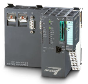
Изделие: 017-CEFPR00
Модуль CPU 017PN: встроенная рабочая память 512 кбайт (расширение до 2 Мбайт), порт 1: Ethernet PG/OP (коммутатор), порт 2: MPI & PtP (RS-485, изолированный), порт 3: MPI (RS-485, изолированный), порт 4: PROFINET I/O (коммутатор), гнездо для карт памяти SD, программирование в SPEED7 Studio, SIMATIC Manager и TIA Portal
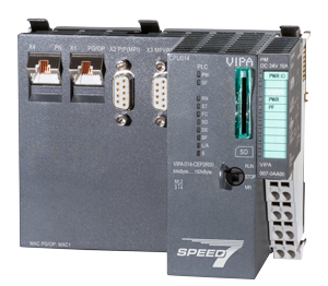
Изделие: 014-CEF0R01
встроенная рабочая память 128 кбайт (расширение до 256 кбайт), порт 1: Ethernet PG/OP (коммутатор), порт 2: MPI & PtP (RS-485, изолированный), порт 3: MPI (RS-485, изолированный), гнездо для карт памяти SD, программирование в SPEED7 Studio, SIMATIC Manager и TIA Portal
Изделие: 014-CEF0R00
Встроенная рабочая память 64 кбайт (расширение до 192 кбайт), порт 1: Ethernet PG/OP, порт 2: MPI & PtP (RS-485, изолированный), порт 3: MPI (RS-485, изолированный), гнездо для карт памяти SD, программирование в WinPLC7, SPEED7 Studio, STEP7 и TIA Portal
Изделие: 015-CEFNR00
Встроенная рабочая память 256 кбайт (расширение до 512 кбайт), порт 1: Ethernet PG/OP (коммут.), порт 2: MPI & PtP (RS-485, изолированный), порт 3: MPI (RS-485, изолированный), порт 4: EtherCAT, порт 5: Ethernet, гнездо для карт памяти SD, программирование в SPEED7 Studio, SIMATIC Manager и TIA Portal
г. Алматы, Ауэзовский район
ул. Толе Би 302, Литер "Д"
офис № 205
+7 (727) 268-0321
+7 (701) 082-9486
+7 (707) 493-7210
+7 (727) 268-0321
info@controllink.kz