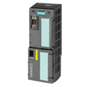
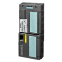
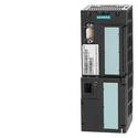
Основное назначение компонента управления Sinamics G120 — обратная связь с инвертором и его контроль. Помимо этого на блоки CU240 могут быть возложены дополнительные задачи. Управляющие модули CU230 используются преимущественно для управления насосами, вентиляторами и компрессорами. Управляющие модули CU230P-2 могут использоваться для управления многими устройствами, в том числе транспортерами, мешалками, экструдерами, мельницы и т.п. Управляющие модули CU240B-2 имеют базовую функциональность и конфигурацию входов-выходов, встроенные интерфейсы USS, Modbus и PROFIBUS. Управляющие модули CU240E-2 имеют стандартную конфигурацию входов-выходов, а также встроенную технику безопасности и дополнительно интерфейс PROFINET. Управляющие модули CU250S-2 дают возможным подключение энкодеров двигателя, управление индукционными двигателями, реализацию задач позиционирования.
Для осуществления управления используются цифровые и аналоговые входы-выходы. Параметры настроек инвертора при необходимости можно сохранить на карте памяти ММС или SD.
В случае замены блока управления CU240 на более продвинутый блок CUA31 появляется возможность централизованного управления приводом при помощи платформы Simotion (с задействованием до 16,32,64 осей).
Example: CU230P-2 PN Control Unit
The CU230P-2 Control Units are designed for drives with integrated technological functions for pump, fan and compressor applications. The I/O interface, the fieldbus interfaces and the additional software functions optimally support these applications.
Note:
Shield plates and shield connection kits are available. These can be used in the wiring installation for the Control Units and PM230/PM240 Power Modules to ensure that it complies with EMC guidelines.
For further information, see Shield connection kits and shield plates for Control Units and Power Modules in section Supplementary system components.
PM330 Power Modules are supplied with the accessories needed to create an EMC-compliant wiring installation for Control Units and Power Modules. The Control Unit mounting surface on the Power Modules has mounting slots for shielding terminals.
Example: CU230P‑2 Control Unit with open and closed terminal covers
|
Terminal No. |
Signal |
Features |
|---|---|---|
|
Digital inputs (DI) – Standard |
||
|
69 |
DI COM |
Reference potential for digital inputs |
|
5 ... 8. |
DI0 … DI5 |
Freely programmable |
|
Digital outputs (DO) |
||
|
18 |
DO0, NC |
Relay output 1 |
|
19 |
DO0, NO |
Relay output 1 |
|
20 |
DO0, COM |
Relay output 1 |
|
21 |
DO1, NO |
Relay output 2 |
|
22 |
DO1, COM |
Relay output 2 |
|
23 |
DO2, NC |
Relay output 3 |
|
24 |
DO2, NO |
Relay output 3 |
|
25 |
DO2, COM |
Relay output 3 |
|
Analog inputs (AI) |
||
|
3 |
AI0+ |
Differential input, switchable between current and voltage |
|
4 |
AI0- |
|
|
10 |
AI1+ |
Differential input, switchable between current and voltage |
|
11 |
AI1- |
|
|
50 |
AI2+ |
Non-isolated input, switchable between current and temperature sensors, type Pt1000/LG-Ni1000 |
|
51 |
GND |
Reference potential of the AI2/internal electronics ground |
|
52 |
AI3+ |
Non-isolated input for temperature sensors, type Pt1000/LG-Ni1000 |
|
53 |
GND |
Reference potential of the AI3/internal electronics ground |
|
Analog outputs (AO) |
||
|
12 |
AO0+ |
Non-isolated output |
|
13 |
GND |
Reference potential of the AO0/internal electronics ground |
|
26 |
AO1+ |
Non-isolated output |
|
27 |
GND |
Reference potential of the AO1/internal electronics ground |
|
Motor temperature sensor interface |
||
|
14 |
T1 MOTOR |
Positive input for motor temperature sensor |
|
15 |
T2 MOTOR |
Negative input for motor temperature sensor |
|
Power supply |
||
|
9 |
+24 V OUT |
Power supply output |
|
28 |
GND |
Reference potential of the power supply/internal electronics ground |
|
1 |
+10 V OUT |
Power supply output |
|
2 |
GND |
Reference potential of the power supply/internal electronics ground |
|
31 |
+24 V IN |
Power supply input |
|
32 |
GND IN |
Reference potential of the power supply input |
|
35 |
+10 V OUT |
Power supply output |
|
36 |
GND |
Reference potential of the power supply/internal electronics ground |
1) The following applies to systems complying with UL: A maximum of 3 A, 30 V DC or 2 A, 250 V AC may be connected via terminals 18 / 20 (DO0 NC) and 23 / 25 (DO2 NC).
Below is a list of functions sorted according to the following categories:
Connection diagram for the CU230P‑2 Control Unit series
Communication interface USS, Modbus RTU, BACnet MS/TP, P1 protocol for CU230P‑2 HVAC
PROFIBUS DP communication interface
Communication interface PROFINET-EtherNet/IP
CANopen communication interface
|
Control Unit |
CU230P‑2 HVAC |
CU230P‑2 DP |
CU230P‑2 PN |
CU230P‑2 CAN |
|---|---|---|---|---|
|
|
6SL3243-0BB30-1HA3 |
6SL3243-0BB30-1PA3 |
6SL3243-0BB30-1FA0 |
6SL3243-0BB30-1CA3 |
|
Electrical specifications |
||||
|
Operating voltage |
24 V DC via the Power Module or by connecting to an external 20.4 ... 28.8 V DC power supply |
|||
|
Current consumption, max. |
0.5 A |
|||
|
Protective insulation |
PELV according to EN 50178 |
|||
|
Power loss, max. |
5 W |
|||
|
Interfaces |
||||
|
Digital inputs – Standard |
6 isolated inputs, optically isolated; NPN/PNP logic can be selected using the wiring |
|||
|
11 V |
|||
|
5 V |
|||
|
5.5 mA |
|||
|
Digital outputs |
3 relays |
|||
|
250 V AC, 2 A (inductive load) |
|||
|
30 V DC, 0.5 A (ohmic load) |
|||
|
Analog inputs |
Analog inputs are protected against inputs in a voltage range of ± 30 V and have a common-mode voltage in the ± 15 V range |
|||
|
Switchable with DIP switch between voltage and current: These differential inputs can be configured as additional digital inputs. |
|||
|
Switchable with DIP switch between 0/4 ... 20 mA current and temperature sensor type Pt1000/LG‑Ni1000, |
|||
|
Temperature sensor type Pt1000/LG‑Ni1000, |
|||
|
Analog outputs |
The analog outputs have short circuit protection |
|||
|
Switchable between voltage and current using parameter setting: Voltage mode: 10 V, min. burden 10 kΩ |
|||
|
PTC/KTY interface |
1 motor temperature sensor input, |
|||
|
Bus interface |
||||
|
Fieldbus protocols |
|
|
|
|
|
Profile |
– |
|
|
– |
|
Hardware |
Plug-in terminal, insulated, |
9-pin SUB-D socket, insulated, |
2 × RJ45, PROFIdrive profile V4.1, device name can be stored on the device Max. 100 Mbit/s (full duplex) |
9-pin SUB-D connector, insulated, |
|
Control Unit |
CU230P‑2 HVAC |
CU230P‑2 DP |
CU230P‑2 PN |
CU230P‑2 CAN |
|---|---|---|---|---|
|
|
6SL3243-0BB30-1HA3 |
6SL3243-0BB30-1PA3 |
6SL3243-0BB30-1FA0 |
6SL3243-0BB30-1CA3 |
|
Tool interfaces |
||||
|
Memory card |
SINAMICS SD card |
|||
|
Operator panels |
|
|||
|
Can be directly plugged on |
|||
|
Can be directly plugged on |
|||
|
Required when no operator panel is plugged in order to achieve degree of protection IP55 on PM230 Power Modules degree of protection IP55/UL Type 12 |
|||
|
PC interface |
USB (connection via PC inverter connection kit 2) |
|||
|
Open-loop/closed-loop control techniques |
||||
|
U/f linear/quadratic/parameterizable |
✓ |
|||
|
U/f with flux current control (FCC) |
✓ |
|||
|
U/f ECO; linear/quadratic |
✓ |
|||
|
Vector control, sensorless |
✓ |
|||
|
Torque control, sensorless |
✓ |
|||
|
Software functions |
||||
|
Setpoint input |
✓ |
|||
|
Fixed frequencies |
16, parameterizable |
|||
|
JOG |
✓ |
|||
|
Digital motorized potentiometer (MOP) |
✓ |
|||
|
Ramp smoothing |
✓ |
|||
|
Extended ramp-function generator (with ramp smoothing OFF3) |
✓ |
|||
|
Slip compensation |
✓ |
|||
|
Signal interconnection with BICO technology |
✓ |
|||
|
Free function blocks (FFB) for logical and arithmetic operations |
✓ |
|||
|
Switchable drive data sets (DDS) |
✓ (4) |
|||
|
Switchable command data sets (CDS) |
✓ (4) |
|||
|
Flying restart |
✓ |
|||
|
Automatic restart after line supply failure or operating fault (AR) |
✓ |
|||
|
Technology controller (internal PID) |
✓ |
|||
|
Sleep mode with internal/external PID controller |
✓ |
|||
|
Belt monitoring with and without sensor (load torque monitoring) |
✓ |
|||
|
Dry-running/overload protection monitoring (load torque monitoring) |
✓ |
|||
|
Thermal motor protection |
✓ (I2t, sensor: PTC/KTY/bimetal) |
|||
|
Thermal inverter protection |
✓ |
|||
|
Motor identification |
✓ |
|||
|
Auto-ramping (Vdcmaxcontroller) |
✓ |
|||
|
Kinetic buffering (Vdcmincontroller) |
✓ |
|||
|
Possible braking functions |
|
|||
|
Control Unit |
CU230P‑2 HVAC |
CU230P‑2 DP |
CU230P‑2 PN |
CU230P‑2 CAN |
|---|---|---|---|---|
|
|
6SL3243-0BB30-1HA3 |
6SL3243-0BB30-1PA3 |
6SL3243-0BB30-1FA0 |
6SL3243-0BB30-1CA3 |
|
Mechanical specifications and ambient conditions |
||||
|
Degree of protection |
IP20 |
|||
|
Signal cable cross-section |
0.15 ... 1.5 mm2 (AWG28 ... AWG16) |
|||
|
Operating temperature |
For CU230P‑2 HVAC/DP/CAN: -10 ... 60 °C (14 ... 140 °F) For CU230P‑2 PN: -10 ... 55 °C (14 ... 131 °F) With IOP/BOP‑2: 0 ... 50 °C (32 ... 122 °F) Derating of 3 K/1000 m applies to Control Units as of an installation altitude of 1000 m (3281 ft) above sea level. |
|||
|
Storage temperature |
-40 ... +70 °C (-40 ... +158 °F) |
|||
|
Relative humidity |
<95 % RH, condensation not permissible |
|||
|
Dimensions |
|
|||
|
73 m (2.87 in) |
|||
|
199 m (7.83 in) |
|||
|
65.5 mm (2.58) |
|||
|
Weight, approx. |
0.61 kg (1.35 lb) |
|||

Изделие: 6SL3246-0BA22-1CA0
SINAMICS G120 БЛОК УПРАВЛЕНИЯ CU250S-2 CAN ВСТРОЕННЫЙ CANOPEN ПОДДЕРЖКА ВЕКТОРНОГО УПРАВЛЕНИЯ, ПРОСТОЕ ПОЗИЦИОНИРОВАНИЕ EPOS VIA EXTENDED FUNCTION LICENSE 4 CONFIGURABLE DI/DO, 6 DI (USABLE AS 3 F-DI), 5 DI, 3 DO (USABLE AS 1 F-DO), 2 AI, 2 AO SAFETY ВСТРОЕННЫЙ STO, SBC, SS1 FURTHER SAFETY FUNCTIONS VIA EXTENDED SAFETY LICENSE ENCODER: D-CLIQ + HTL/TTL/SSI, RESOLVER/HTL VIA TERMINAL PROTECTION IP20 USB- AND SD/MMC-INTERFACE

Изделие: 6SL3244-0BB13-1FA0
SINAMICS G120 МОДУЛЬ УПРАВЛЕНИЯ CU240E-2 PN-F E-TYPE ВСТРОЕННАЯ БЕЗОПАСНОСТЬ STO, SS1, SLS, PROFINET 6DI, 3DO, 2AI, 2AO, MAX 3F-DI PTC/KTY ИНТЕРФЕЙС USB- И SD/MMC-ИНТЕРФЕЙС ЗАЩИТА IP20 ОКРУЖ. ТЕМП. 0 TO +50 ГРД C СOUT СИЛОВЫМ МОДУЛЕМ И ПАНЕЛЬЮ

Изделие: 6SL3246-0BA22-1PA0
SINAMICS G120 БЛОК УПРАВЛЕНИЯ CU250S-2 DP ВСТРОЕННЫЙ PROFIBUS ПОДДЕРЖКА ВЕКТОРНОГО УПРАВЛЕНИЯ, ПРОСТОЕ ПОЗИЦИОНИРОВАНИЕ EPOS VIA EXTENDED FUNCTION LICENSE 4 CONFIGURABLE DI/DO, 6 DI (USABLE AS 3 F-DI), 5 DI, 3 DO (USABLE AS 1 F-DO), 2 AI, 2 AO SAFETY ВСТРОЕННЫЙ STO, SBC, SS1 FURTHER SAFETY FUNCTIONS VIA EXTENDED SAFETY LICENSE ENCODER: D-CLIQ + HTL/TTL/SSI, RESOLVER/HTL VIA TERMINAL PROTECTION IP20 USB- AND SD/MMC-INTERFACE

Изделие: 6SL3243-0BB30-1HA3
SINAMICS G120 БЛОК УПРАВЛЕНИЯ CU230P-2 HVAC USS/ MODBUS RTU/BACNET MS/TP 6 DI, 3 DO, 4 AI, 2 AO 1 ДАТЧИК ТЕМП. ДВИГАТЕЛЯ ВХОД 2 PSU-OUT(10V DC, 24V DC) 1 PSU-IN (24V DC) USB- AND MMC-ЗАЩИТА ИНТЕРФЕЙСА IP20