Компактная система управления представляет собой универсальное решение, объединяюще в себе панель оператора ОР и PLC-CPU 100V. Используется для отображения и управления небольшими пользовательскими приложениями, написанными с помощью программного обеспечения OP Manager или ProTool (SIEMENS). Позволяет отображать текстовые сообщения о статусе, режиме, рецептуре, авариях, а также задавать уставки переменным с помощью навигационных и функциональных кнопок.
|
Наименование
|
Компактная система управления |
|
Тип
|
CC 03 |
|
Описание
|
LCD экран на 2х20 символов, интегрированный PLC-CPU c MP²I интерфейсом, 16 x DI, 16 x DO, 128 kB пользовательской памяти, 4096 переменных |
|
Напряжение питания
|
DC 24V |
|
Степень защиты
|
IP 65 |
|
Интерфейс/коммуникации
|
MP²I |
|
Монтаж
|
щитовой |
|
Габарит
|
187 х 90 х 61 мм |
|
Температура окружающей среды
|
работа: 0…+60°С хранение: -20…+70°С |
|
Серия
|
Commander Compact |
|
Диагональ
|
2х20 символов |
 |
|
 |
|

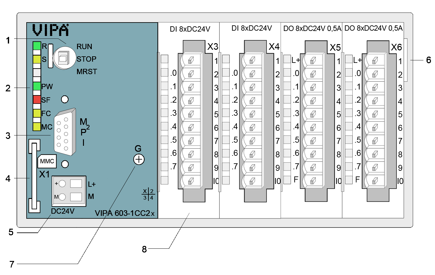
LEDs
| Label | Color | Description |
| R | Green | CPU is in the operating mode RUN |
| S | Yellow | CPU is in the operating mode STOP |
| PW | Green | CPU portion is supplied internal |
| SF | Red | On at system error (hardware failure) |
| FC | Yellow | On as soon as variables are forced* |
| MC | Yellow |
Shows access to MMC * |
* only back side
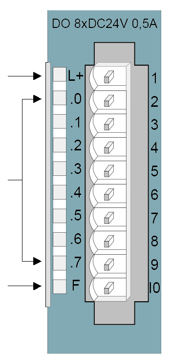
Status monitor pin assignment
| LED | Description | Digital Input | Assignment | |
| .0... .7 |
LEDs (green) |
 |
|
|
| L+ |
LED (green) |
 |
|
|
| .0... .7 |
LEDs (green) |
|||
| F |
LED (red) |

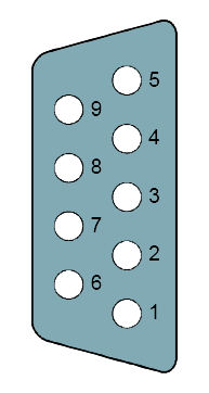
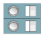
| MP2I | Описание | DC 24V | Описание | |||
 |
|
 |
|
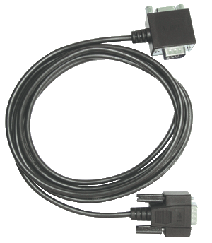 |
Кабель программирования670-0KB00 Для VIPA CC 03, OP 03 и TD 03, соединители 0°/90°, длина 2,5 м |
 |
Кабель программирования670-0KB01 Для VIPA CC 03, OP 03 и TD 03, соединители 90°/90°, длина 2,5 м |
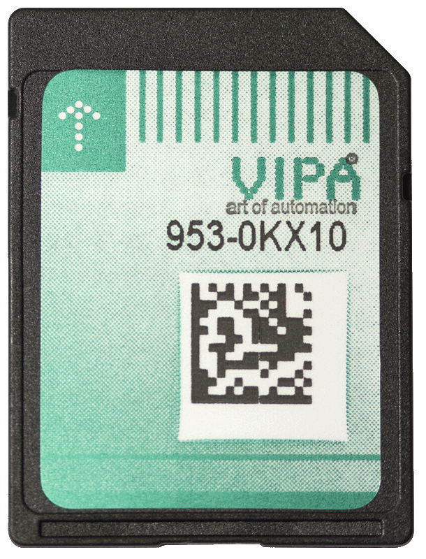 |
Карта памяти MMC953-0KX10 Емкость 512 Мбайт |
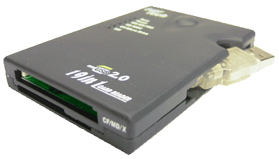 |
Устройство для программирования карт памяти MMC950-0AD00 Интерфейс USB (Windows 2000/XP) |
Order no. |
603-1CC22 |
| Type | CC 03, Commander Compact |
General information |
|
| Note | - |
| Features | Display: 2 x 20 characters Interface: MP²I User memory: 128 kB Languages: DE, EN, FR, ES, IT, SV, NO, DA Project engineering via VIPA OP-Manager or Siemens ProTool Integrated PLC-CPU: 24/32kByte work/load memory, 16 x DI, 16 x DO, up to 4 I/O expansion modules |
Display |
|
| Number of rows | 2 |
| Characters per row | 20 |
| Character height | 5 mm |
| Type of display | STN with LED backlighting |
OP functionality |
|
| User memory | 128 KB |
| Number of variables | 4096 |
| Language | DE/EN/FR/ES/IT/SV/NO/DA |
Operating controls |
|
| Touchscreen | - |
| Mouse | - |
| Number of system keys | 8 |
| Number of soft keys | 5 |
Technical data power supply |
|
| Power supply (rated value) | DC 24 V |
| Power supply (permitted range) | DC 20.4...28.8 V |
| Reverse polarity protection |  |
| Current consumption (no-load operation) | 130 mA |
| Current consumption (rated value) | 1 A |
| Inrush current | 60 A |
| I²t | 0.35 A²s |
| Max. current drain at backplane bus | 0.8 A |
| Power loss | 8 W |
| Reverse polarity protection |  |
Technical data digital inputs |
|
| Number of inputs | 16 |
| Cable length, shielded | 1000 m |
| Cable length, unshielded | 600 m |
| Rated load voltage | DC 24 V |
| Reverse polarity protection of rated load voltage |  |
| Current consumption from load voltage L+ (without load) | - |
| Rated value | DC 24 V |
| Input voltage for signal "0" | DC 0...5 V |
| Input voltage for signal "1" | DC 15...28.8 V |
| Input current for signal "1" | 7 mA |
| Connection of Two-Wire-BEROs possible |  |
| Max. permissible BERO quiescent current | 1.5 mA |
| Input delay of "0" to "1" | 3 ms |
| Input delay of "1" to "0" | 3 ms |
| Input characteristic curve | IEC 61131-2, type 1 |
| Initial data size | 2 Byte |
Technical data digital outputs |
|
| Number of outputs | 16 |
| Cable length, shielded | 1000 m |
| Cable length, unshielded | 600 m |
| Rated load voltage | DC 24 V |
| Reverse polarity protection of rated load voltage | - |
| Current consumption from load voltage L+ (without load) | 50 mA |
| Total current per group, horizontal configuration, 40°C | 4 A |
| Total current per group, horizontal configuration, 60°C | 4 A |
| Total current per group, vertical configuration | 4 A |
| Output voltage signal "1" at min. current | L+ (-125 mV) |
| Output voltage signal "1" at max. current | L+ (-0.8 V) |
| Output current at signal "1", rated value | 0.5 A |
| Output delay of "0" to "1" | max. 100 µs |
| Output delay of "1" to "0" | max. 350 µs |
| Minimum load current | - |
| Lamp load | 5 W |
| Switching frequency with resistive load | max. 1000 Hz |
| Switching frequency with inductive load | max. 0.5 Hz |
| Switching frequency on lamp load | max. 10 Hz |
| Internal limitation of inductive shut-off voltage | L+ (-52 V) |
| Short-circuit protection of output | yes, electronic |
| Trigger level | 1 A |
| Output data size | 2 Byte |
Technical data counters |
|
| Number of counters | - |
| Counter width | - |
| Maximum input frequency | - |
| Maximum count frequency | - |
| Mode incremental encoder | - |
| Mode pulse / direction | - |
| Mode pulse | - |
| Mode frequency counter | - |
| Mode period measurement | - |
| Gate input available | - |
| Latch input available | - |
| Reset input available | - |
| Counter output available | - |
Status information, alarms, diagnostics |
|
| Status display | yes |
| Interrupts | no |
| Process alarm | yes |
| Diagnostic interrupt | yes |
| Diagnostic functions | no |
| Diagnostics information read-out | possible |
| Supply voltage display | green LED |
| Group error display | red SF LED |
| Channel error display | red LED per group |
Isolation |
|
| Between channels of groups to | 8 |
| Between channels and backplane bus |  |
| Insulation tested with | DC 500 V |
Technical data power supply |
|
| Power supply (rated value) | DC 24 V |
| Power supply (permitted range) | DC 20.4...28.8 V |
| Reverse polarity protection |  |
| Current consumption (no-load operation) | 130 mA |
| Current consumption (rated value) | 1 A |
| Inrush current | 60 A |
| I²t | 0.35 A²s |
| Max. current drain at backplane bus | 0.8 A |
| Max. current drain load supply | - |
| Power loss | 8 W |
Load and working memory |
|
| Load memory, integrated | 32 KB |
| Load memory, maximum | 32 KB |
| Work memory, integrated | 24 KB |
| Work memory, maximal | 24 KB |
| Memory divided in 50% program / 50% data | - |
| Memory card slot | MMC-Card with max. 512 MB |
Hardware configuration |
|
| Racks, max. | 1 |
| Modules per rack, max. | 4 |
| Number of integrated DP master | 0 |
| Number of DP master via CP | 4 |
| Operable function modules | 4 |
| Operable communication modules PtP | 4 |
| Operable communication modules LAN | - |
Command processing times |
|
| Bit instructions, min. | 0.25 µs |
| Word instruction, min. | 1.2 µs |
| Double integer arithmetic, min. | 2.6 µs |
| Floating-point arithmetic, min. | 50 µs |
Timers/Counters and their retentive characteristics |
|
| Number of S7 counters | 256 |
| S7 counter remanence | adjustable 0 up to 64 |
| S7 counter remanence adjustable | C0 .. C7 |
| Number of S7 times | 256 |
| S7 times remanence | adjustable 0 up to 128 |
| S7 times remanence adjustable | not retentive |
Data range and retentive characteristic |
|
| Number of flags | 8192 Bit |
| Bit memories retentive characteristic adjustable | adjustable 0 up to 256 |
| Bit memories retentive characteristic preset | MB0 .. MB15 |
| Number of data blocks | 2047 |
| Max. data blocks size | 16 KB |
| Number range DBs | 1 ... 2047 |
| Max. local data size per execution level | 1024 Byte |
| Max. local data size per block | 1024 Byte |
Blocks |
|
| Number of OBs | 14 |
| Maximum OB size | 16 KB |
| Total number DBs, FBs, FCs | - |
| Number of FBs | 1024 |
| Maximum FB size | 16 KB |
| Number range FBs | 0 ... 1023 |
| Number of FCs | 1024 |
| Maximum FC size | 16 KB |
| Number range FCs | 0 ... 1023 |
| Maximum nesting depth per priority class | 8 |
| Maximum nesting depth additional within an error OB | 4 |
Time |
|
| Real-time clock buffered |  |
| Clock buffered period (min.) | 30 d |
| Type of buffering | Vanadium Rechargeable Lithium Battery |
| Load time for 50% buffering period | 20 h |
| Load time for 100% buffering period | 48 h |
| Accuracy (max. deviation per day) | 10 s |
| Number of operating hours counter | 8 |
| Clock synchronization | - |
| Synchronization via MPI | no |
| Synchronization via Ethernet (NTP) | no |
Address areas (I/O) |
|
| Input I/O address area | 1024 Bit |
| Output I/O address area | 1024 Bit |
| Process image adjustable | - |
| Input process image preset | 128 Byte |
| Output process image preset | 128 Byte |
| Input process image maximal | 128 Byte |
| Output process image maximal | 128 Byte |
| Digital inputs | 8192 |
| Digital outputs | 8192 |
| Digital inputs central | 144 |
| Digital outputs central | 144 |
| Integrated digital inputs | 16 |
| Integrated digital outputs | 16 |
| Analog inputs | 512 |
| Analog outputs | 512 |
| Analog inputs, central | 32 |
| Analog outputs, central | 16 |
| Integrated analog inputs | - |
| Integrated analog outputs | - |
Communication functions |
|
| PG/OP channel |  |
| Global data communication |  |
| Number of GD circuits, max. | 4 |
| Size of GD packets, max. | 22 Byte |
| S7 basic communication |  |
| S7 basic communication, user data per job | 76 Byte |
| S7 communication |  |
| S7 communication as server |  |
| S7 communication as client | - |
| S7 communication, user data per job | 160 Byte |
| Number of connections, max. | 16 |
Functionality Sub-D interfaces |
|
| Type | MP²I |
| Type of interface | RS485 |
| Connector | Sub-D, 9-pin, female |
| Electrically isolated | - |
| MPI |  |
| MP²I (MPI/RS232) |  |
| DP master | - |
| DP slave | - |
| Point-to-point interface | - |
| Type | - |
| Type of interface | - |
| Connector | - |
| Electrically isolated | - |
| MPI | - |
| MP²I (MPI/RS232) | - |
| DP master | - |
| DP slave | - |
| Point-to-point interface | - |
Functionality MPI |
|
| Number of connections, max. | 16 |
| PG/OP channel |  |
| Routing | - |
| Global data communication |  |
| S7 basic communication |  |
| S7 communication |  |
| S7 communication as server |  |
| S7 communication as client | - |
| Transmission speed, min. | 19.2 kbit/s |
| Transmission speed, max. | 187.5 kbit/s |
Functionality PROFIBUS slave |
|
| PG/OP channel | - |
| Routing | - |
| S7 communication | - |
| S7 communication as server | - |
| S7 communication as client | - |
| Direct data exchange (slave-to-slave communication) | - |
| DPV1 | - |
| Transmission speed, min. | - |
| Transmission speed, max. | - |
| Automatic detection of transmission speed | - |
| Transfer memory inputs, max. | - |
| Transfer memory outputs, max. | - |
| Address areas, max. | - |
| User data per address area, max. | - |
Mechanical data |
|
Housing / Protection type |
|
| Material | die-cast aluminum |
| Mounting | via integrated pivoted lever |
| Protect type front side | IP 65 |
| Protect type back side | IP 20 |
Dimensions |
|
| Front panel | 187 mm x 90 mm x 6 mm |
| Rear panel | 154 mm x 77 mm x 55 mm |
Installation cut-out |
|
| Width | 156 mm |
| Height | 78 mm |
| Minimum | 2.5 mm |
| Maximum front panel thickness | 6 mm |
| Weight | 580 g |
Environmental conditions |
|
| Operating temperature | 0 °C to 60 °C |
| Storage temperature | -20 °C to 70 °C |
Certifications |
|
| UL508 certification | yes |
| Order no. | Name/Description | |
|---|---|---|
|
603-1CC21 |
CC 03 - Commander Compact Display: 2 x 20 characters Interface: MP²I User memory: 128 kB Languages: DE, EN, FR, ES, IT, SV, NO, DA Project engineering via VIPA OP-Manager or Siemens ProTool Integrated PLC-CPU: 16/24kByte work/load memory, 16 x DI, 16 x DO, up to 4 I/O expansion modules |
|
|
603-1CC22 |
CC 03 - Commander Compact Display: 2 x 20 characters Interface: MP²I User memory: 128 kB Languages: DE, EN, FR, ES, IT, SV, NO, DA Project engineering via VIPA OP-Manager or Siemens ProTool Integrated PLC-CPU: 24/32kByte work/load memory, 16 x DI, 16 x DO, up to 4 I/O expansion modules |
|
|
603-1CC23 |
CC 03 - Commander Compact Display: 2 x 20 characters Interface: MP²I User memory: 128 kB Languages: DE, EN, FR, ES, IT, SV, NO, DA Project engineering via VIPA OP-Manager or Siemens ProTool Integrated PLC-CPU: 32/40kByte work/load memory, 16 x DI, 16 x DO, up to 4 I/O expansion modules |
|
|
603-1OP00 |
OP 03 - Operator Panel Display: 2 x 20 characters Interface: MP²I User memory: 256 kB Languages: DE, EN, FR, ES, IT, SV, NO, DA Project engineering via VIPA OP-Manager or Siemens ProTool |
|
|
603-1OP10 |
OP 03 - Operator Panel Display: 2 x 20 characters Interface: MP²I User memory: 256 kB Languages: DE (without Umlaut), EN, RU Project engineering only via VIPA OP-Manager |
|
|
603-1TD00 |
TD 03 - Text Display␍ Display: 2 x 20 characters Interface: MP²I Languages: DE, EN Visualization of the connected CPU via MPI |
|
|
603-2CC21 |
CC 03 - Commander Compact Display: 2 x 20 characters Interface: MP²I , PROFIBUS-DP slave User memory: 128 kB Languages: DE, EN, FR, ES, IT, SV, NO, DA Project engineering via VIPA OP-Manager or Siemens ProTool Integrated PLC-CPU: 16/24kByte work/load memory, 16 x DI, 16 x DO, up to 4 I/O expansion modules |
|
|
603-2CC22 |
CC 03 - Commander Compact Display: 2 x 20 characters Interface: MP²I, PROFIBUS-DP slave User memory: 128 kB Languages: DE, EN, FR, ES, IT, SV, NO, DA Project engineering via VIPA OP-Manager or Siemens ProTool Integrated PLC-CPU: 24/32kByte work/load memory, 16 x DI, 16 x DO, up to 4 I/O expansion modules |
|
|
603-2CC23 |
CC 03 - Commander Compact Display: 2 x 20 characters Interface: MP²I, PROFIBUS-DP slave User memory: 128 kB Languages: DE, EN, FR, ES, IT, SV, NO, DA Project engineering via VIPA OP-Manager or Siemens ProTool Integrated PLC-CPU: 32/40kByte work/load memory, 16 x DI, 16 x DO, up to 4 I/O expansion modules |
|
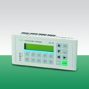
Изделие: 603-2CC21
Дисплей 2x20 символов, встроенный ПЛК с памятью 16 кбайт/24 кбайт (рабочая/загрузочная), порт MP2I, порт PROFIBUS DP (ведомое устройство), встроенные DI 16x24 В пост. тока, DO 16x24 В/0,5 А пост. тока, до 4 модулей расширения

Изделие: 603-1CC23
Дисплей 2x20 символов, встроенный ПЛК с памятью 32 кбайт/40 кбайт (рабочая/загрузочная), порт MP2I, встроенные DI 16x24 В пост. тока, DO 16x24 В/0,5 А пост. тока, до 4 модулей расширения

Изделие: 603-1CC21
Дисплей 2x20 символов, встроенный ПЛК с памятью 16 кбайт/24 кбайт (рабочая/загрузочная), порт MP2I, встроенные DI 16x24 В пост. тока, DO 16x24 В/0,5 А пост. тока, до 4 модулей расширения

Изделие: 603-2CC23
Дисплей 2x20 символов, встроенный ПЛК с памятью 32 кбайт/40 кбайт (рабочая/загрузочная), порт MP2I, порт PROFIBUS DP (ведомое устройство), встроенные DI 16x24 В пост. тока, DO 16x24 В/0,5 А пост. тока, до 4 модулей расширения