Модуль дискретного ввода для систем безопасности, 4 канала 24 В пост. тока
|
Наименование
|
Модуль дискретных входов SM 021, 4 inputs, Safety |
|
Тип
|
021-1SD00 |
|
Габаритные размеры, В х Ш х Г, мм
|
12.9 mm x 109 mm x 76.5 mm |
|
Температура окружающей среды
|
0 °C .. 60 °C |
|
Количество входов
|
4 |
|
Тип входного сигнала
|
24VDC |
 |
|
Status indication
 |
RUN | MF | Description |
| green | red |
|
|
| ● | ○ | Bus communication is OK Module status is OK |
|
| ● | ● |
Bus communication is OK |
|
| ○ | ● |
Bus communication is not possible |
|
| ○ | ○ | Error at bus power supply | |
| B | B |
Error in configuration |
|
| on: ● | off: ○ | blinking with 0.5Hz: B | |||
| LED | Color | Description | |
| PS | green | ● |
PROFIsafe communication in data exchange |
| BB | Safety parametrization expected | ||
| B | Error - acknowledgement expected | ||
| ○ | Module initialization is running | ||
| ERR | red | ● | Permanent fail-safe condition |
| C | Blink code | ||
| ERR2 | yellow | C | Blink code |
| B | Requesting fail-safe state | ||
| DI x | green | ● | Digital input is triggered |
|
on: ● | off: ○ | blinking with 0.5Hz: B | blinking with 2Hz: BB | Blink code: C |
|||
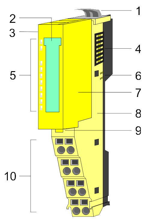
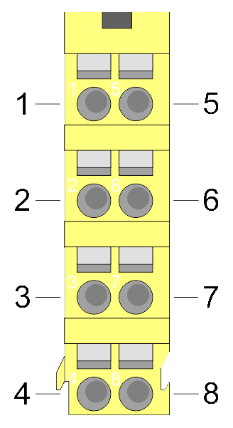
Pin assignment
| PM - Power module | Pos. | Function |
Type |
Description | |
 |
1 | DI 0 | I | Digital input DI 0 | |
| 2 | DI 2 | I |
Digital input DI 2 |
||
| 3 | T0 | O |
Clock output T0 |
||
| 4 | T2 | O | Clock output T2 | ||
| 5 | DI 1 | I | Digital input DI 1 | ||
| 6 | DI 3 | I |
Digital input DI 3 |
||
| 7 | T1 | O |
Clock output T1 |
||
| 8 | T3 | O | Clock output T3 |
I: Input, O: Output
Order no. |
021-1SD00 |
| Type | SM 021 |
| Module ID | 0C41 2E00 |
General information |
|
| Note | - |
| Features | 4 inputs Safety |
Current consumption/power loss |
|
| Current consumption from backplane bus | 95 mA |
| Power loss | 0.8 W |
Technical data digital inputs |
|
| Number of inputs | 4 |
| Cable length, shielded | 330 m |
| Cable length, unshielded | 330 m |
| Rated load voltage | - |
| Current consumption from load voltage L+ (without load) | 2 mA |
| Rated value | DC 20.4...28.8 V |
| Input voltage for signal "0" | DC 0...5 V |
| Input voltage for signal "1" | DC 11...28.8 V |
| Input voltage hysteresis | - |
| Frequency range | - |
| Input resistance | - |
| Input current for signal "1" | 3 mA |
| Connection of Two-Wire-BEROs possible |  |
| Max. permissible BERO quiescent current | 1.5 mA |
| Input delay of "0" to "1" | parameterizable 1ms - 1s |
| Input delay of "1" to "0" | parameterizable 1ms - 1s |
| Number of simultaneously utilizable inputs horizontal configuration | 4 |
| Number of simultaneously utilizable inputs vertical configuration | 4 |
| Input characteristic curve | IEC 61131-2, type 3 |
| Initial data size | 4 Bit |
Status information, alarms, diagnostics |
|
| Status display | green LED per channel |
| Interrupts | yes, parameterizable |
| Process alarm | no |
| Diagnostic interrupt | yes, parameterizable |
| Diagnostic functions | yes, parameterizable |
| Diagnostics information read-out | possible |
| Module state | green LED |
| Module error display | red LED |
| Channel error display | red ERR-LED and yellow ER2-LED |
Isolation |
|
| Between channels | - |
| Between channels of groups to | - |
| Between channels and backplane bus |  |
| Insulation tested with | DC 500 V |
Safety |
|
| Safety protocol | PROFIsafe V2 |
| Safety requirements | SIL CL 3, PL e, Kat 4 |
| Secure user address | 1 - 4095 |
| Watchdog | parameterizable 10ms - 1s |
| Two channels | Each 2 of 4 inputs switchable |
| Test pulse outputs | 4 |
Datasizes |
|
| Input bytes | 5 |
| Output bytes | 5 |
| Parameter bytes | 44 |
| Diagnostic bytes | 20 |
Housing |
|
| Material | PC / PPE GF10 |
| Mounting | Profile rail 35 mm |
Mechanical data |
|
| Dimensions (WxHxD) | 12.9 mm x 109 mm x 76.5 mm |
| Weight | 60 g |
Environmental conditions |
|
| Operating temperature | 0 °C to 60 °C |
| Storage temperature | -25 °C to 70 °C |
Certifications |
|
| UL508 certification | in preparation |
| Order no. | Name/Description | |
|---|---|---|
|
021-1BB00 |
SM 021 - Digital input 2 inputs |
|
|
021-1BB10 |
SM 021 - Digital input 2 fast inputs Input filter time delay parameterizable 2 µs...4 ms |
|
|
021-1BB50 |
SM 021 - Digital input 2 inputs Active low input |
|
|
021-1BB70 |
SM 021 - Digital input 2 inputs Time stamp |
|
|
021-1BD00 |
SM 021 - Digital input 4 inputs |
|
|
021-1BD10 |
SM 021 - Digital input 4 fast inputs Input filter time delay parameterizable 2 µs...4 ms |
|
|
021-1BD40 |
SM 021 - Digital input 4 inputs Connect 2/3-wire |
|
|
021-1BD50 |
SM 021 - Digital input 4 inputs Active low input |
|
|
021-1BD70 |
SM 021 - Digital input 4 inputs Time stamp |
|
|
021-1BF00 |
SM 021 - Digital input 8 inputs |
|
|
021-1BF01 |
SM 021 - Digital input 8 Inputs, 0.5ms |
|
|
021-1BF50 |
SM 021 - Digital input 8 inputs Active low input |
|
|
021-1DF00 |
SM 021 - Digital input 8 inputs diagnosis of wiring errors |
|
|
021-1SD00 |
SM 021 - Digital input 4 inputs Safety |
|
|
022-1BB00 |
SM 022 - Digital output 2 outputs Output current 0.5 A |
|
|
022-1BB20 |
SM 022 - Digital output 2 outputs Output current 2 A |
|
|
022-1BB50 |
SM 022 - Digital output 2 Low-Side outputs Output current 0.5 A |
|
|
022-1BB70 |
SM 022 - Digital output 2 outputs Time stamp Output current 0.5 A |
|
|
022-1BB90 |
SM 022 - Digital output 2 outputs PWM |
|
|
022-1BD00 |
SM 022 - Digital output 4 outputs Output current 0.5 A |
|
|
022-1BD20 |
SM 022 - Digital output 4 outputs Output current 2 A |
|
|
022-1BD50 |
SM 022 - Digital output 4 Low-Side outputs Output current 0.5 A |
|
|
022-1BD70 |
SM 022 - Digital output 4 outputs Time stamp Output current 0.5 A |
|
|
022-1BF00 |
SM 022 - Digital output 8 outputs Output current 0.5 A |
|
|
022-1BF50 |
SM 022 - Digital output 8 Low-Side outputs Output current 0.5 A |
|
|
022-1DF00 |
SM 022 - Digital output 8 outputs Output current 0.5 A diagnosis of wiríng errors |
|
|
022-1HB10 |
SM 022 - Digital output 2 relay outputs DC 30 V/ AC 230 V Output current 3 A |
|
|
022-1SD00 |
SM 022 - Digital output 4 outputs Safety Output current 0.5 A |
|

Изделие: 021-1BD40
4 канала 24 В пост. тока, 2/3-проводная схема подключения

Изделие: 021-1BF50
8 каналов 24 В пост. тока, отрицательная логика

Изделие: 021-1BF01
8 каналов 24 В пост. тока, задержка входного сигнала 0,5 мс