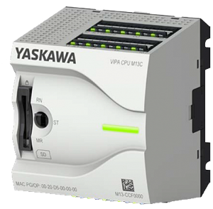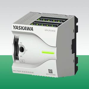
В программе поставок известного разработчика и производителя программируемых логических контроллеров немецкой компании VIPA появилась серия ПЛК MICRO, что знаменует собой смену поколений устройств данного типа. Изделия новой линейки выгодно отличаются современным дизайном, небольшими размерами, многократно возросшей производительностью и высокой плотностью каналов.
Благодаря новинке пользователь получает в свое распоряжение суперкомпактную высокопроизводительную систему управления с очень привлекательной ценой. В модулях применены инновационные линейные индикаторы, позволяющие с одного взгляда легко и быстро оценить состояние оборудования.
Высочайшая производительность контроллеров MICRO, обеспеченная использованием технологии SPEED7, позволяет им легко справляться с задачами точного позиционирования и сложными алгоритмами управления. Встроенный порт Ethernet (PG/OP, Modbus TCP и др.) является основным коммуникационным интерфейсом контроллеров. Обмен в режимах PROFIBUS Slave, PtP и MPI реализуется с помощью опционального модуля расширения, а вся память контроллера является энергонезависимой.
С ПЛК MICRO не нужно изучать новые языки программирования, а при работе использовать весь опыт и навыки, накопленные для Simatic S7-300. Для программирования контроллера, помимо бесплатного пакета VIPA SPEED7 Studio Lite, доступны разнообразные программные средства производства VIPA или Siemens.
| Power supply: | DC 24V |
| Working memory integrated: | 64kByte |
| Working memory expandable up to: | 128kByte |
| Load memory | 128kByte |
| Ports: | 2 Ethernet PG/OP(switch) |
SD card slot. Programmable via WinPLC7, SPEED7 Studio, SIMATIC Manager and TIA Portal
| Модуль CPU 015PN | Описание | |
 |
|
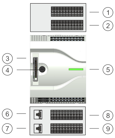
Интерфейсы
|
X3/X4 PG/OP |
Описание | |
 |
|
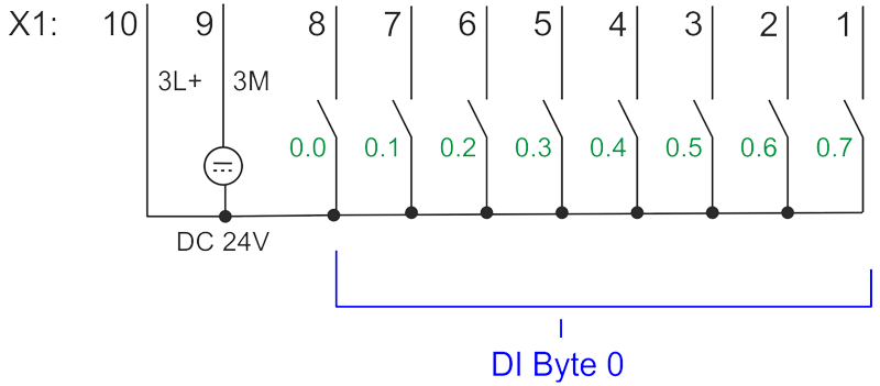
| X1: DI byte 0 | ||||
 |
||||
| Function | Type | Description | ||
| 1 | DI 0.7 | I | green | Digital input DI 7 / Counter 2 (B) / Frequency 2 * |
| 2 | DI 0.6 | I | green | Digital input DI 6 / Counter 2 (A) * |
| 3 | DI 0.5 | I | green | Digital input DI 5 |
| 4 | DI 0.4 | I | green | Digital input DI 4 / Counter 1 (B) / Frequency 1 * |
| 5 | DI 0.3 | I | green | Digital input DI 3 / Counter 1 (A) * |
| 6 | DI 0.2 | I | green | Digital input DI 2 |
| 7 | DI 0.1 | I | green | Digital input DI 1 / Counter 0 (B) / Frequency 0 * |
| 8 | DI 0.0 | I | green | Digital input DI 0 / Counter 0 (A) * |
| 9 | 0 V | I | green | 3M: GND for onboard DI power section supply |
| 10 | DC 24V | I | green | 3L+: DC 24V for onboard DI power section supply |
| *) Max. input frequency 100kHz otherwise 1kHz. | ||||
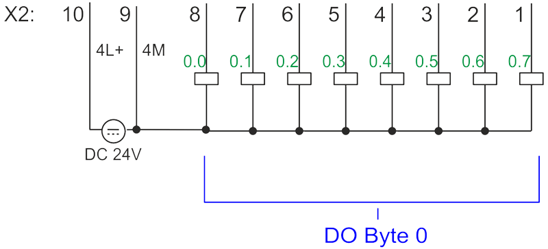
| X2: DO byte 0 | ||||
 |
||||
| Function | Type | Description | ||
| 1 | DO 0.7 | O | green | Digital output DO 7 |
| 2 | DO 0.6 | O | green | Digital output DO 6 |
| 3 | DO 0.5 | O | green | Digital output DO 5 |
| 4 | DO 0.4 | O | green | Digital output DO 4 |
| 5 | DO 0.3 | O | green | Digital output DO 3 / Output channel counter 3 |
| 6 | DO 0.2 | O | green | Digital output DO 2 / Output channel counter 2 |
| 7 | DO 0.1 | O | green | Digital output DO 1 / PWM 1 / Output channel counter 1 |
| 8 | DO 0.0 | O | green | Digital output DO 0 / PWM 0 / Output channel counter 0 |
| 9 | 0 V | I | red |
4M: GND for onboard DO power section supply / GND PWM |
| 10 | DC 24V | I | green | 4L+: DC 24V for onboard DO power section supply |
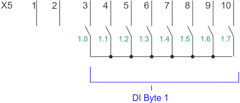
| X5: DI byte 1 | ||||
 |
||||
| Function | Type | Description | ||
| 1 | - | - | reserved | |
| 2 | - | - | reserved | |
| 3 | DI 1.0 | I | green | Digital input DI 8 |
| 4 | DI 1.1 | I | green | Digital input DI 9 / Counter 3 (A) * |
| 5 | DI 1.2 | I | green | Digital input DI 10 / Counter 3 (B) / Frequency 3 * |
| 6 | DI 1.3 | I | green | Digital input DI 11 / Gate 3 * |
| 7 | DI 1.4 | I | green | Digital input DI 12 |
| 8 | DI 1.5 | I | green | Digital input DI 13 |
| 9 | DI 1.6 | I | green | Digital input DI 14 |
| 10 | DI 1.7 | I | green | Digital input DI 15 / Latch 3 * |
| *) Max. input frequency 100kHz otherwise 1kHz. | ||||
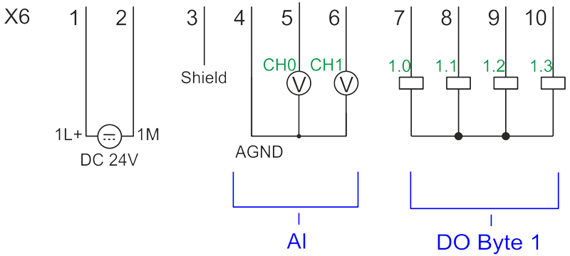
| X6: DC 24V, AI, DO byte 1 | ||||
 |
||||
| Function | Type | Description | ||
| 1 | Sys DC 24V | I | green | 1L+: DC 24V for electronic section supply |
| 2 | Sys 0V | I | 1M: GND for electronic section supply | |
| 3 | Shield | I | Shield | |
| 4 | AGND | I | GND for analog inputs | |
| 5 | AI 0 | I | Analog input AI 0 | |
| 6 | AI 1 | I | Analog input AI 1 | |
| 7 | DO 1.0 | O | green | Digital output DO 8 |
| 8 | DO 1.1 | O | green | Digital output DO 9 |
| 9 | DO 1.2 | O | green | Digital output DO 10 |
| 10 | DO 1.3 | O | green | Digital output DO 11 |
Order no. |
M13-CCF0000 |
| Type | CPU M13C |
| Module ID | - |
General information |
|
| Note | - |
| Features | SPEED7 technology 16 x DI, 12 x DO, 2 x AI, from which are 4 input channels parameterizable for counters and frequency measurement and 2 Output channels for PWM 64 kB work memory Memory extension (max. 128 kB) optionell PROFIBUS-DP slave / PtP (switchable) |
Technical data power supply |
|
| Power supply (rated value) | DC 24 V |
| Power supply (permitted range) | DC 20.4...28.8 V |
| Reverse polarity protection |  |
| Current consumption (no-load operation) | 120 mA |
| Current consumption (rated value) | 360 mA |
| Inrush current | 3 A |
| I²t | 0.1 A²s |
| Max. current drain at backplane bus | 1 A |
| Max. current drain load supply | - |
| Power loss | 7 W |
Load and working memory |
|
| Load memory, integrated | 128 KB |
| Load memory, maximum | 128 KB |
| Work memory, integrated | 64 KB |
| Work memory, maximal | 128 KB |
| Memory divided in 50% program / 50% data | |
| Memory card slot | SD/MMC-Card with max. 2 GB |
Hardware configuration |
|
| Racks, max. | 1 |
| Modules per rack, max. | 8 |
| Number of integrated DP master | - |
| Number of DP master via CP | - |
| Operable function modules | - |
| Operable communication modules PtP | - |
| Operable communication modules LAN | - |
Command processing times |
|
| Bit instructions, min. | 0.02 µs |
| Word instruction, min. | 0.02 µs |
| Double integer arithmetic, min. | 0.02 µs |
| Floating-point arithmetic, min. | 0.12 µs |
Timers/Counters and their retentive characteristics |
|
| Number of S7 counters | 512 |
| S7 counter remanence | adjustable 0 up to 256 |
| S7 counter remanence adjustable | C0 .. C7 |
| Number of S7 times | 512 |
| S7 times remanence | adjustable 0 up to 256 |
| S7 times remanence adjustable | not retentive |
Data range and retentive characteristic |
|
| Number of flags | 8192 Byte |
| Bit memories retentive characteristic adjustable | adjustable 0 up to 256 |
| Bit memories retentive characteristic preset | MB0 .. MB15 |
| Number of data blocks | 1024 |
| Max. data blocks size | 64 KB |
| Number range DBs | 1 ... 4095 |
| Max. local data size per execution level | 4096 Byte |
| Max. local data size per block | 4096 Byte |
Blocks |
|
| Number of OBs | 22 |
| Maximum OB size | 64 KB |
| Total number DBs, FBs, FCs | 1024 |
| Number of FBs | 1024 |
| Maximum FB size | 64 KB |
| Number range FBs | 0 ... 4095 |
| Number of FCs | 1024 |
| Maximum FC size | 64 KB |
| Number range FCs | 0 ... 4095 |
| Maximum nesting depth per priority class | 16 |
| Maximum nesting depth additional within an error OB | 4 |
Time |
|
| Real-time clock buffered | |
| Clock buffered period (min.) | 30 d |
| Type of buffering | Goldcap |
| Load time for 50% buffering period | 15 min |
| Load time for 100% buffering period | 1 h |
| Accuracy (max. deviation per day) | 10 s |
| Number of operating hours counter | 8 |
| Clock synchronization | |
| Synchronization via MPI | Master/Slave |
| Synchronization via Ethernet (NTP) | no |
Address areas (I/O) |
|
| Input I/O address area | 2048 Byte |
| Output I/O address area | 2048 Byte |
| Process image adjustable | |
| Input process image preset | 128 Byte |
| Output process image preset | 128 Byte |
| Input process image maximal | 2048 Byte |
| Output process image maximal | 2048 Byte |
| Digital inputs | 144 |
| Digital outputs | 140 |
| Digital inputs central | 144 |
| Digital outputs central | 140 |
| Integrated digital inputs | 16 |
| Integrated digital outputs | 12 |
| Analog inputs | 2 |
| Analog outputs | 0 |
| Analog inputs, central | 2 |
| Analog outputs, central | 0 |
| Integrated analog inputs | 2 |
| Integrated analog outputs | 0 |
Communication functions |
|
| PG/OP channel | |
| Global data communication | |
| Number of GD circuits, max. | 8 |
| Size of GD packets, max. | 54 Byte |
| S7 basic communication | |
| S7 basic communication, user data per job | 76 Byte |
| S7 communication | |
| S7 communication as server | |
| S7 communication as client | - |
| S7 communication, user data per job | 160 Byte |
| Number of connections, max. | 32 |
PWM data |
|
| PWM channels | 2 |
| PWM time basis | 1 µs / 0.1 ms / 1 ms |
| Period length | - |
| Minimum pulse width | 0...0.5 * Period duration |
| Type of output | Highside |
Functionality Sub-D interfaces |
|
| Type | X1 |
| Type of interface | RS422/485 isolated |
| Connector | Sub-D, 9-pin, female |
| Electrically isolated | |
| MPI | - |
| MP²I (MPI/RS232) | - |
| DP master | - |
| DP slave | - |
| Point-to-point interface | |
| 5V DC Power supply | max. 90mA, isolated |
| 24V DC Power supply | - |
| Type | X2 |
| Type of interface | RS485 isolated |
| Connector | Sub-D, 9-pin, female |
| Electrically isolated | |
| MPI | |
| MP²I (MPI/RS232) | - |
| DP master | - |
| DP slave | optional |
| Point-to-point interface | - |
| 5V DC Power supply | max. 90mA, isolated |
| 24V DC Power supply | - |
Functionality MPI |
|
| Number of connections, max. | 32 |
| PG/OP channel | |
| Routing | |
| Global data communication | |
| S7 basic communication | |
| S7 communication | |
| S7 communication as server | |
| S7 communication as client | - |
| Transmission speed, min. | 19.2 kbit/s |
| Transmission speed, max. | 12 Mbit/s |
Functionality PROFIBUS slave |
|
| PG/OP channel | |
| Routing | |
| S7 communication | |
| S7 communication as server | |
| S7 communication as client | - |
| Direct data exchange (slave-to-slave communication) | - |
| DPV1 | |
| Transmission speed, min. | 9.6 kbit/s |
| Transmission speed, max. | 12 Mbit/s |
| Automatic detection of transmission speed | |
| Transfer memory inputs, max. | 244 Byte |
| Transfer memory outputs, max. | 244 Byte |
| Address areas, max. | 32 |
| User data per address area, max. | 32 Byte |
Point-to-point communication |
|
| PtP communication | |
| Interface isolated | |
| RS232 interface | - |
| RS422 interface | |
| RS485 interface | |
| Connector | Sub-D, 9-pin, female |
| Transmission speed, min. | 150 bit/s |
| Transmission speed, max. | 115.2 kbit/s |
| Cable length, max. | 500 m |
Point-to-point protocol |
|
| ASCII protocol | |
| STX/ETX protocol | |
| 3964(R) protocol | |
| RK512 protocol | - |
| USS master protocol | |
| Modbus master protocol | |
| Modbus slave protocol | |
| Special protocols | - |
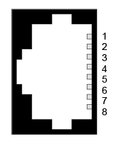
Functionality RJ45 interfaces |
|
| Type | - |
| Type of interface | Ethernet 10/100 MBit Switch |
| Connector | 2 x RJ45 |
| Electrically isolated | |
| PG/OP channel | |
| Number of connections, max. | 4 |
| Productive connections | |
| Fieldbus | - |
| Type | - |
| Type of interface | - |
| Connector | - |
| Electrically isolated | - |
| PG/OP channel | - |
| Number of connections, max. | - |
| Productive connections | - |
| Fieldbus | - |
Ethernet communication via PG/OP |
|
| Number of productive connections via PG/OP, max. | 2 |
| Number of productive connections by Siemens NetPro, max. | 2 |
| S7 connections | BSEND, BRCV, GET, PUT, Connection of active and passive data handling |
| User data per S7 connection, max. | 64 KB |
| TCP-connections | FETCH PASSIV, WRITE PASSIV, Connection of passive data handling |
| User data per TCP connection, max. | 8 KB |
| ISO on TCP connections (RFC 1006) | FETCH PASSIV, WRITE PASSIV, Connection of passive data handling |
| User data per ISO connection, max. | 8 KB |
Ethernet open communication via PG/OP |
|
| Number of configurable connections, max. | 2 |
| ISO on TCP connections (RFC 1006) | TSEND, TRCV, TCON, TDISCON |
| User data per ISO on TCP connection, max. | 32 KB |
| TCP-Connections native | TSEND, TRCV, TCON, TDISCON |
| User data per native TCP connection, max. | 32 KB |
| User data per ad hoc TCP connection, max. | 1460 Byte |
| UDP-connections | TUSEND, TURCV |
| User data per UDP connection, max. | 1472 Byte |
Housing |
|
| Material | PPE / PPE GF10 |
| Mounting | Profile rail 35 mm |
Mechanical data |
|
| Dimensions (WxHxD) | 72 mm x 88 mm x 71 mm |
| Net weight | 221 g |
| Weight including accessories | 221 g |
| Gross weight | 240 g |
Environmental conditions |
|
| Operating temperature | 0 °C to 60 °C |
| Storage temperature | -25 °C to 70 °C |
Certifications |
|
| UL certification | in preparation |
| KC certification | in preparation |
| Order no. | Name/Description | |
|---|---|---|
|
M13-CCF0000
|
CPU M13C - powered by SPEED7 |
|
|
M21-1BH00 |
SM M21 - Digital input |
|
|
M22-1BH00 |
SM M22 - Digital output |
|
|
M23-1BH00 |
SM M23 - Digital output |
|
|
M09-0CB00
|
Micro Extension 2xRS485 |
|

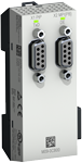
Изделие: M22-1BH00
Модуль дискретного вывода SM M22, 16 каналов 24 В/0,5 А пост. тока
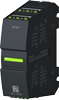
Изделие: M09-0CB00
Коммуникационный модуль IM M09, порт RS-485 (MPI, PROFIBUS Slave), порт RS-422/485 (ASCII, STX/ETX, 3964(R), USS master, Modbus master)

Изделие: M23-1BH00
Модуль дискретного ввода/вывода SM M23, 8 каналов DI 24 В пост. тока, 8 каналов DO 24 В/0,5 А пост. тока
Изделие: M21-1BH00
Модуль дискретного ввода SM M21, 16 каналов 24 В пост. тока
г. Алматы, Ауэзовский район
ул. Толе Би 302, Литер "Д"
офис № 205
+7 (727) 268-0321
+7 (701) 082-9486
+7 (707) 493-7210
+7 (727) 268-0321
info@controllink.kz